

Why uncoordinated models fail and how architectural and structural bim services fix them
Architects and structural engineers often work in parallel but separate environments. The architect focuses on spatial layout, building envelope aesthetics, and interior finishes. The structural engineer calculates gravity loads, lateral forces, and designs the concrete or steel frame. When these models are not actively federated, the gap between design intent and physical reality is resolved on the job site through expensive change orders. Utilizing integrated design coordination resolves these conflicts during the preconstruction phase by merging both models into a single coordinated environment.
This process relies on a federated model acting as a single source of truth. When the architectural shell and the structural frame combine, design teams run automated clash detection routines. This is not just about finding where a steel beam physically cuts through a window. It is about understanding assembly tolerances. For instance, a concrete column might fit within a partition wall on paper. But when you factor in structural tolerances for concrete pouring, which can be up to 25 millimeters, plus the thickness of drywall finishes, the wall suddenly bulges into a corridor. This violates building codes for minimum egress width. Identifying this digitally allows the architect to shift the wall partition or the engineer to modify the column profile before ordering materials.
Transitioning from isolated designs to coordinated bim coordination workflows drastically reduces field questions. Instead of the field team stopping work to write a request for information, the coordination team resolves the discrepancy during weekly meetings. This proactive approach keeps the field crew focused on assembly rather than problem solving, protecting the project timeline and the developer contingency fund.
Why do paper based constructability reviews always miss structural clashes?
Paper reviews, even when performed using digital PDF overlays, rely entirely on human eyes to spot discrepancies across hundreds of sheets. A reviewer must compare a structural framing plan on sheet S102 with an architectural ceiling plan on sheet A405 while mentally calculating the vertical elevations of both systems. When a 400 millimeter structural beam cuts through a ceiling plenum packed with architectural finishes and lighting pockets, the conflict is almost impossible to spot on a flat page. The human brain cannot consistently project three dimensional space across multiple flat documents, which is why structural clashes slip through to the field.
A coordinate based 3D environment eliminates this cognitive load. By utilizing software like Autodesk Revit and Navisworks, the coordination team can isolate specific zones, such as the ceiling plenum in a high density corridor, and run hard clash algorithms. The software instantly flags every instance where a structural element occupies the same physical coordinates as an architectural element. The team resolves these issues systematically, adjusting beam depths or ceiling heights in the model before fabricators begin cutting steel or casting concrete.
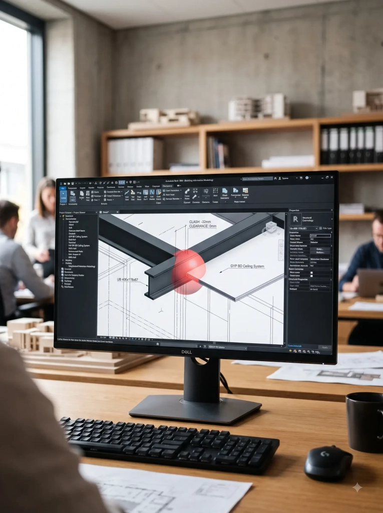
Can you coordinate architectural elements without structural steel models?
Attempting to coordinate architectural detailing, such as exterior curtain walls, masonry ties, or interior partition tracks, without an accurate structural BIM modeling file is a recipe for field disaster. Structural steel is fabricated in a controlled shop environment to millimeter precision, but concrete foundations and structural steel frames deflect under load. If the architectural team designs facade attachments based on nominal structural drawings rather than the fabricated steel model, the brackets will not fit the physical steel on site.
To prevent this, the coordination team must work with models built to at least LOD 350. At this level, the model contains actual steel connection plates, gussets, bolt patterns, and weldments. When the architectural cladding is coordinated against this level of structural detail, fabricators can predrill attachment holes in the shop rather than requiring field welding or drilling on live steel, which is slow and expensive. This precision is especially important for complex geometries, such as cantilevered entrance canopies or sloping roofs, where architectural form is entirely dependent on structural integrity.
Moving from reactive clash detection to proactive spatial coordination
Too many project teams treat clash detection as a final gatekeeping step, a box to check right before construction begins. By that point, the design is 95 percent complete. Changing a major structural member or architectural layout causes a domino effect of redesign costs and schedule delays. True spatial coordination is an iterative process that must begin during the schematic design phase and continue through construction documentation. It requires a cultural shift from finding clashes to preventing them through disciplined modeling standards.
One of the most common oversights in this process is failing to model clearances, also known as soft clashes. A soft clash occurs when elements do not physically touch but violate code clearances, maintenance access zones, or structural deflection limits. For example, a heavy structural steel girder will deflect downwards when the concrete floor slab is poured above it. If the architectural ceiling or interior partition wall is modeled tight to the underside of the steel beam without accounting for this deflection, the downward movement of the beam will crush the partition wall on site. Proactive coordination involves modeling a deflection zone, a clear space where no architectural elements can be placed, to ensure the building can flex under load without damaging finishes.
Another area is the coordination of expansion joints. Large scale buildings require structural expansion joints to allow the building to move during thermal changes or seismic events. These joints must cut through both the structural frame and the architectural finishes, including floors, walls, and ceilings. If the architectural team does not coordinate finish plans with structural expansion joint locations, you end up with expansion covers cutting through high end lobby finishes or blocking access doors. Coordinated modeling ensures these joints are integrated into the aesthetic design of the space rather than treated as an afterthought in the field.
Does high LOD modeling really pay off on medium sized projects?
Developers of medium sized commercial or residential buildings often hesitate to invest in high Level of Development modeling, viewing it as an unnecessary expense. They assume that because the building is straightforward, the field crews can work out the details on site. This is a costly misunderstanding of modern construction economics. The cost of labor on site is significantly higher than the cost of virtual design coordination, and field modifications carry a heavy premium in both time and material waste. Look, it is not perfect. But it is the most practical workaround we have right now to keep subcontractors from pointing fingers at each other when things do not fit.
Consider a simple concrete framed multifamily residential building. If the structural columns are modeled to LOD 300 instead of LOD 350, which includes detailed reinforcement and sleeve locations, the team cannot coordinate plumbing penetrations through the structural slab. When the concrete is poured, the plumbing sleeves are often placed in the wrong positions because they had to avoid the rebar layout, which was not visible in the low LOD model. The result is a series of misaligned pipes that require core drilling or furring out walls in the apartments, reducing the usable floor area and delaying drywall installation. A single day of delay for a drywall crew on a medium sized project can cost more than the entire fee for detailed architectural BIM services.
How do structural slab penetrations delay architectural finishes?
Slab penetrations for mechanical, electrical, and plumbing systems are the primary source of conflict between structural frames and architectural layouts. In high rise residential or commercial office builds, hundreds of pipes and ducts must pass through concrete slabs on every floor. If these penetrations are not coordinated with the structural framing plan, they will conflict with post tensioning cables, structural beams, or heavy rebar zones.